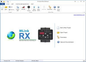
Take your motor protection to a new level. The RX Series provides more than just solid state overload or power protection relays. By using features previously found only in large expensive Motor Protection Relays, the RX Series allows even small to medium sized motor applications to be protected by the best technology available, yet at a price affordable to all.
Advanced Technology for Maximum Motor and System Protection
The RX Series uses Thermal Modeling software normally found only in the most sophisticated Motor Protection Relays. This software keeps track of power related issues occurring in the motor circuit that contribute to causing a thermal overload. If there is a power loss, a unique combination of non-volatile memory and a real-time clock ensure that this protection is in effect when power is restored. Should an overload occur, the RX Series is intelligent enough to make sure that it can only be reset when the motor is sufficiently cooled down and is ready to start again successfully. Voltage input features allow true Motor Load Monitoring, not just current, along with Power Factor, kVA and Frequency.
Built-in Flexible Control Features Provide Cost and Space Savings
A 24 hour / 7 day Real Time Clock on board allows for several additional features that can eliminate the need for other discrete devices. Duty cycle can be controlled by using the Starts/Hour and Minimum Time Between Starts features, plus a Coast-Down / Backspin timer can prevent restarting while a motor is spinning backwards. In addition, simple Batch Time processes of up to 7 events can be programmed for daily, multi-day or weekly operations without the need for an external time clock. A Restart Delay timer allows staggered restarting of multiple units as well.
Add Metering and Communications to New or Existing Starters
Metering for Three Phase Currents, Voltages, kW, kVA, kVAR, Power Factor, Frequency, kWH, Elapsed Run Time, Run Cycle Count, Lock-Out Time, Reset Time and Remaining Thermal Capacity are all included, and can be both read on the display and communicated via the built-in RS-485 Modbus RTU comm. Port. Optional converters allow communications via DeviceNet, Field Bus, Profibus and other protocols as well. Fault memory with time and date stamps helps in troubleshooting and returning to operation.
True Thermal Modeling
Advanced Motor Protection
Metering for Three Phase Currents, Voltages
, kW, kVA, kVAR, Power Factor, Frequency, kWH, Elapsed Run Time, Run Cycle Count, Lock-Out Time, Reset Time and Remaining Thermal Capacity
Real-time Clock
DIN-Rail Mount
RS485 Modbus RTU
| Design | ||||||
| Type of Load | 3-phase AC induction motors | |||||
| AC Supply Voltage (Motor Voltage) | Direct: 200 - 600VAC, ± 10%, 50/60hz With 120V PTs: 690 - 15,000VAC | |||||
| Current Range | 1 - 2000 Amps in 3 frame ratings | |||||
| Sevice Factor | Programmable from 1.00 to 1.30 for NEMA design motors | |||||
| Current Measurement | 3 window CTs on units up to 75A, external CTs for higher ratings (meets NEC requirments for 3-leg protection) | |||||
| Power Wiring | Direct feed-through or external CT lead feed-through | |||||
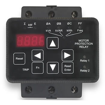
| LED Display and Keypad | 7-segment, 4-digit alpha-numeric display designed for use in high ambient light conditions. Full function, 4- quadrant navigation keys for easy access to status information and programmable functions | |||||
| LED Status Lights | 10 LED indicators on the front panel for relay status | |||||
| Control | ||||||
| Control Voltage | Universal voltage supply, 85 - 265VAC or DC, 50/60Hz | |||||
| Multi-function Digital Input | One (1) dry contact input for Timer Start, Remote Start or Remote Trip | |||||
| Fault Reset | Manual reset via the keypad or cycle control power for remote reset | |||||
| Programmable Output Contacts | One (1) Form C (SPDT) 5A, 240VAC maximum One (1) Form A (SPST) 10A maximum, 1/2 HP @ 240VAC 29 programmable trip functions | |||||
| Event Timer Control | 24 hr, 7 day, 7 event timer allows automatic start w/ batch run time control | |||||
| Batch Run Timer Control | Minimum run timer (resumes timing if stopped) or permissive run timer (only runs during set time). Time setting: 1 - 9999 minutes. | |||||
| Protection | ||||||
| Overload Protection Method | Real-time Motor Thermal Modeling uses current sensors and microprocessor to continuously calculate motor temperature | |||||
| Retentive Thermal Memory | Remembers the thermal condition of the motor even if control power is lost. Thermal register is adjusted for Off-time when power is restored. | |||||
| Dual Overload Curve Settings | Two separately programmable overload trip curves; one for starting and one for running. OL trip range: Class 5 - 30. | |||||
| Learned Dynamic Reset | Automatically adjusts other settings to compensate for programmed Service Factory. Adjustment Range: 1.0 - 1.15 SF. | |||||
| Programmable Service Factor | Automatically adjusts other settings to compensate for programmed Service Factory. Adjustment Range: 1.0 - 1.15 SF. | |||||
| Current Imbalance Protection | Monitors phase-to-phase current levels and trips if imbalance exceeds setting. Setting: Off or 5 - 30% of FLA with 1-20 second delay. | |||||
| Phase Loss / Sequence Protection | Trips if any phase < 20% FLA. Sequence selectable A-B-C, C-A-B or Off. | |||||
|
|
|||||
| Over Voltage Trip (any phase) | Setting: Off or 1-10% of set voltage with 1-20 second delay | |||||
|
|
|||||
| Load Monitor | Under or over kW trip or alarm. Setting: Off or 20 - 100% of motor kW with 1-20sec delay | |||||
| Power Factor Monitor | Leading or lagging PF, trip or alarm. Setting: Off or 0.1 - 1.0PF (lead or lag) with 1-20 second delay | |||||
| Frequency Monitor | Over or under programmed frequency. Setting: Off or 1-10Hz with 1-20sec delay | |||||
| Equipment Ground Fault Protection | Electronic residual current protection method, no additional CTs needed. Setting: Off or 5-90% of CT with 1-60sec delay | |||||
| Short Circuit / Shorted Load | Peak current quick trip (electronic fuse). Trip level: Off or 800-1400% FLA with 0.1 - 0.5sec delay | |||||
| Restart Delay Timer | Programmable delay of restart after a power failure. Setting: 0 - 999 sec. | |||||
| Starts-per-Hour Lockout | Program maximum starts-per-hour in adherence with motor design limitations. Setting: Off or 0 - 10 starts/Hr. | |||||
| Minimum Time between Starts | Used with or without starts-per-hour protection to prevent short cycling of motor. Setting: Off or 1 - 60 minutes between starts | |||||
| Coast-Down Timer | Back spin or anti-windmillling protection prevents restart after stop command has been given. Time setting: Off or 1 - 3600 seconds. | |||||
| Metering | ||||||
| Amp Meter (each phase) | Default is Phase A, scroll up or down for phases B, C and ground. 0 - 9999A (999A for ground), ± 2% accuracy |
|||||
| Volt Meter (each phase) | 0-600V, or 1-15kV, ± 2% accuracy. Displays total voltage imbalance as %. | |||||
| Elapsed Time Meter | Running time from at-speed detection. Resettable only with passwrd. Range: 0 - 9,999,999.9 hours. |
|||||
| Run Cycle Counter | Counts number of starts (at-speed) for maintenance, etc. Resettable only with password. Range: 0 - 99,999,999 counts. |
|||||
| Power Metering | kW, kWHr, kVA, kVAR, or MW, MWHr, MVA, MVAR. 0 - 9999 units, ± 2% accuracy |
|||||
| Power Factor Metering | Leading (inductive) or lagging (capacitive), 0.1 - 1.0 PF | |||||
| Display | ||||||
| Fault Display | Fault code indicator plus 10 LEDs for phase and trip status. | |||||
| Fault Event Recorder | Records and displays previous three (3) fault trips (stored in non-volatile memory). Time and date stamped. Cleared only with password. |
|||||
| Thermal Capacity | Real-time display of motor's remaining thermal capacity after starting or running. Value shown as 0 - 100% (counts upwards while cooling). |
|||||
| Remaining Time | View values of lockout times such as time-between-starts or coast-down timer. View process timer or time clock values. | |||||
| Environmental Conditions & Approvals | ||||||
| Standard Packaging | Protected Chassis (IP00) with DIN rail adaptor | |||||
| Remote Display Mounting | Built in operator interface can be remote mounted up to 10ft (3 meters) away. NEMA 4/12 mounting kit optional. |
|||||
| Altitude | Up to 10,000 feet (3000 meters) without derating | |||||
| Ambient Temperature | 0° C to 50°C (32°F to 122°F), 0 to 95% relative humidity | |||||
| Approvals | UL, CUL, CE | |||||
| ZCT Option | 68 KB : Installation and Info Sheet | Rev 1.00 |
 RX Brochure 2.63 MB (PDF)